During a four-week summer term at BCIT in the Electrical Engineering Program, one of our courses is an Electronics System Design Project. Teams of two set out to create a robot capable of navigating an obstacle course and firing pellets at four targets before crossing a finishing line.

The obstacle course is fitted with four targets, one on each wall. These four targets and several of the corners of the walls are fitted with ArUco markers. In addition to the physical system there is a camera mounted above the arena connected to a server that allows for data collection from the arena.
Manual Mode
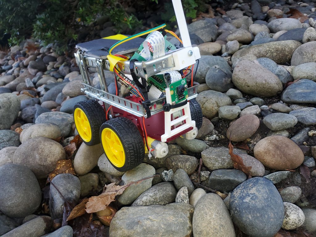
1. Seeing the challenge my partner and I set out to add another. We wanted to be the fastest team to complete the project and we wanted to do it while spending as little as possible. According to our professor the fasted team to complete in all years past finished the Friday of the 3rd week. Our goal was to blow this out of the water and we would succeed. We finished the teleoperation mode by Thursday of the first week and the autonomous mode by Thursday of the second week. This meant we had to optimize. While most teams set out to 3d print a chassis to conceal their wiring we focused on the strictly necessary details. The motors, launcher, batteries and camera had to be stable, everything else was extra.
Photo of CAR
2. We then decided to split the job into two parts. First physical design and wiring, and Second control and software. I was tasked with control and software so that is what I will be explaining. We ran into two major issues integration and reliability.
3. The first design I was tasked with doing was modifying a PI HAT for our needs. We needed motor control, servo control, and a status light.
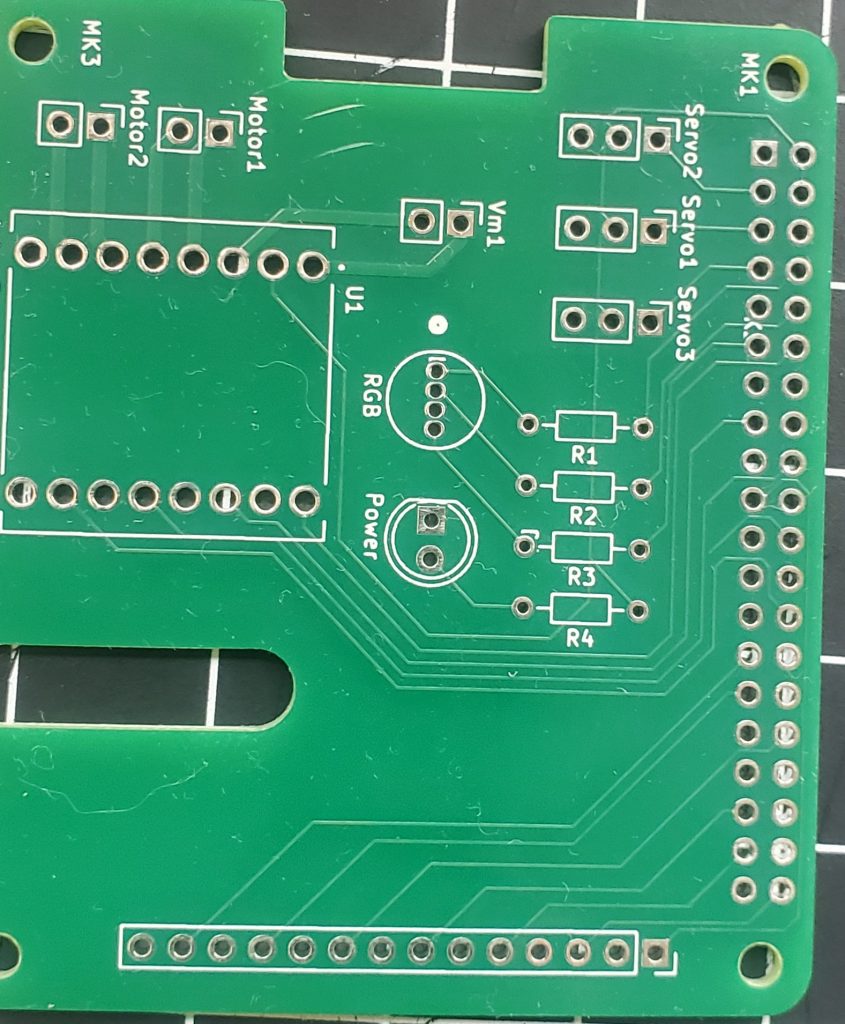
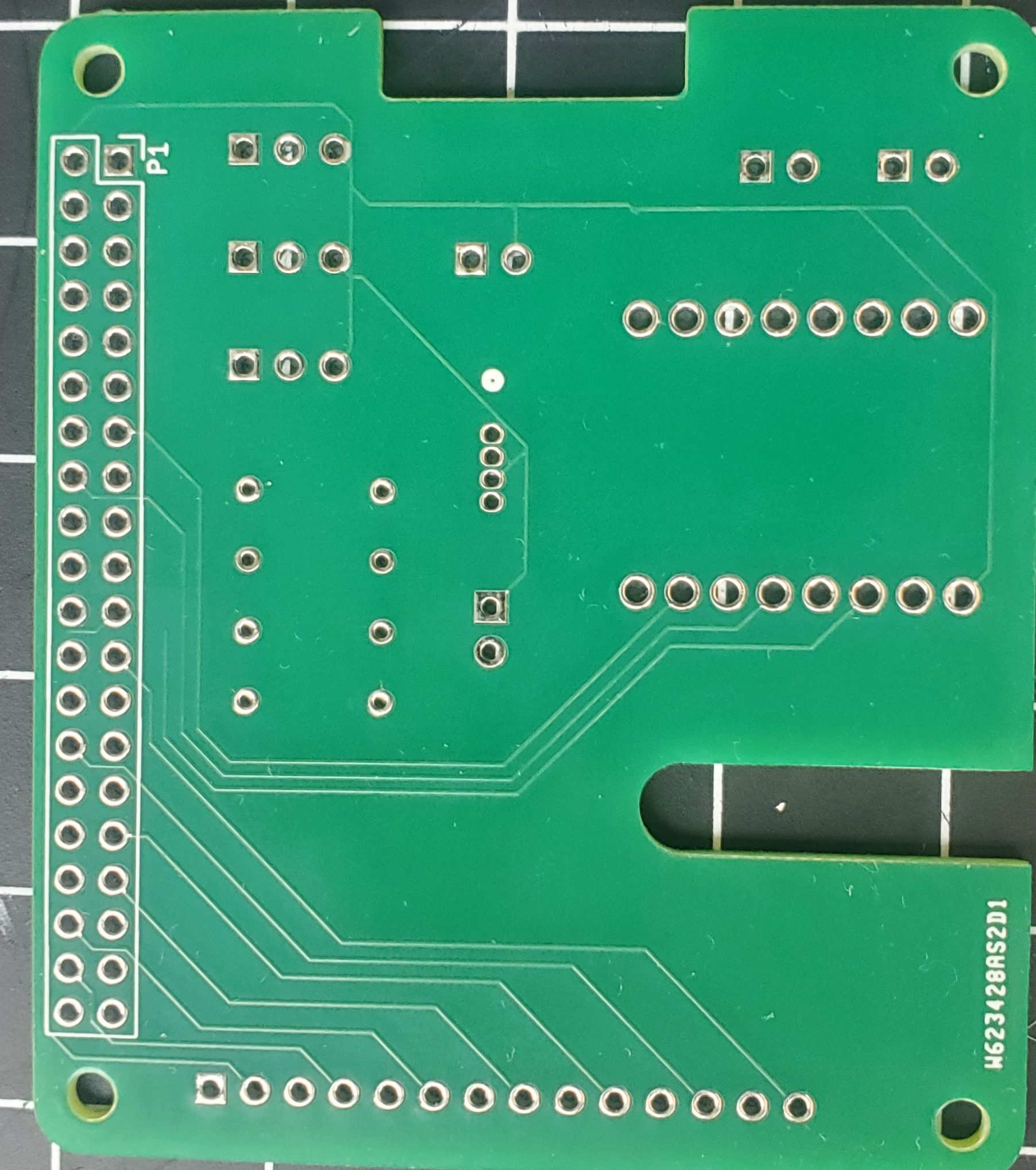
4. One of our goal was to minimize budget as much as possible. With this in mind we re used many components from previous projects and lab kits. In a previous course we did some basic motor driving with a TB6612FNG dual H-bridge. It was this chip I based the design around. Because we were aiming to complete the system in record time the design had to be simple. Placed two pinouts for the motors connected to the pinouts for the H-bridge. Then a simple pinout for the motors’ external power and status light. I then connected three of the PI GPIO pins to servo pinouts and the rest to a general connector for incase we overlooked anything. This simple design allowed us to build the simple system we needed without worry of design error. This was key if we had to order another board we would have blown our timeline.
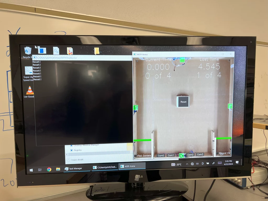
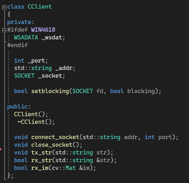
5. Next I worked on server connection. Our professor setup a server for the arena. Using this server you can pull start time, target states, run time, and the camera image. In a previous course we developed the CClient class which uses iostream and Hans De Reuters Serial class.
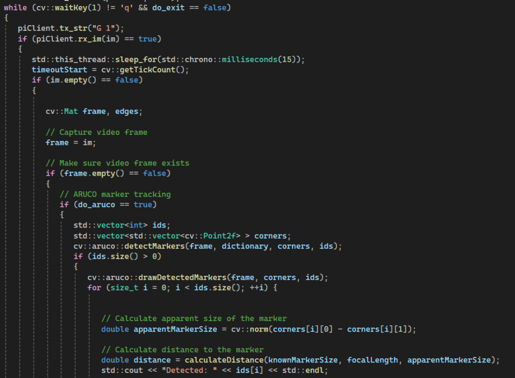
6. The arena server was setup to respond to two commands “G 0” returns a text string containing the information mentioned above and “G 1” returns the current frame captured by the camera. I focused on gaining access to the camera first as it would allow me to test my server connection clearly.
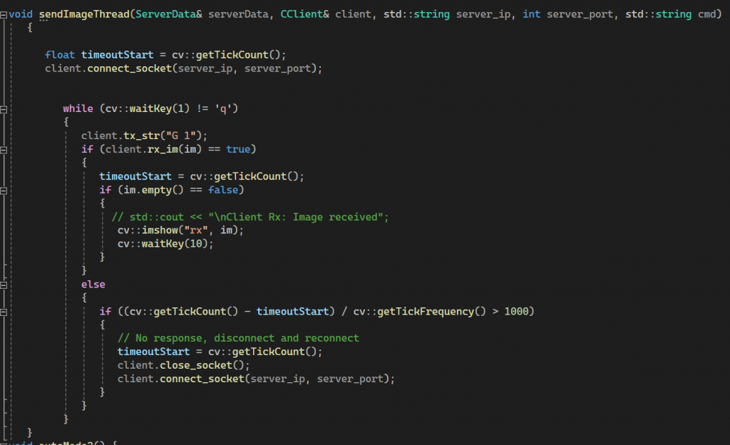
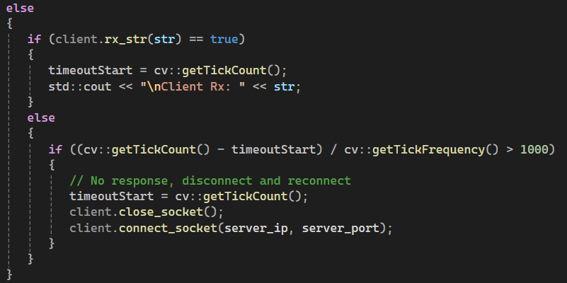
7. This code grabs a fame 100 times a second as long as the frame is new and not empty. If the server is timed out it disconnects the socket. The biggest key to our operation was threading it separate from the PI server.
8. The next connection is the PI server this is two parts first we need to setup the Raspberry PI to operate as a server while simultaneously doing motor control
PI SERVER CODE
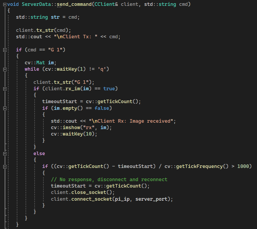
9. Once we have setup the Raspberry PI as a server we must setup the client to communicate with the PI. We decided to use the same notation for all server communication. That is either G or S for Get or Send then a number for register and a number for data type. Eg: S 1 1 would be read as Send Motors State1. This roughly follows the notation we used in our previous C++ class when doing server communications. For our PI server I needed two communications get image or send command.
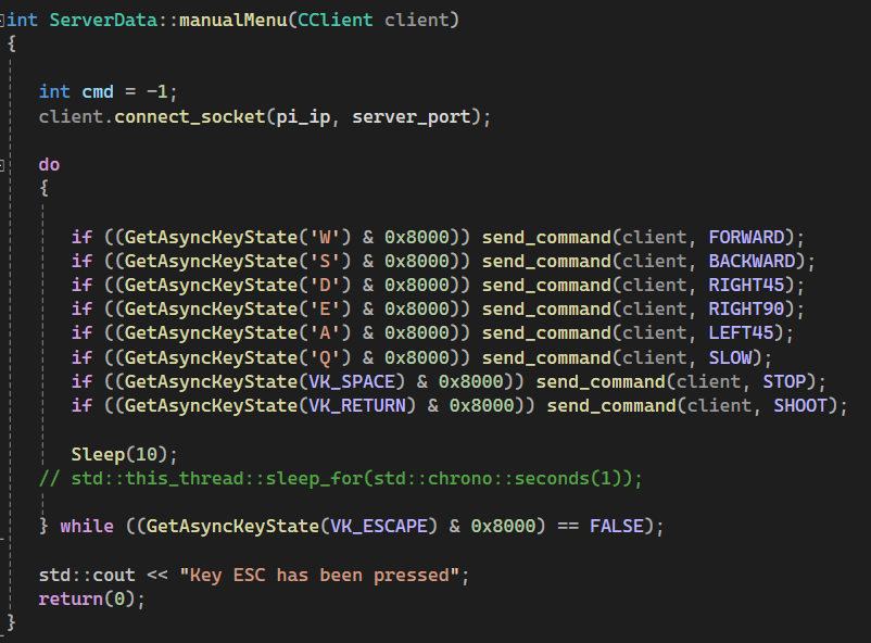
10. Now I set out to make a manual mode. I wanted simple controls that match most video games. WASD to move and stop when no key is pressed. For this I made a simple do while loop that checked key states. I ended up using Q and E to allow for fine control when turning.
11. With manual mode complete we have finished task 1 and the majority of the the project. What had taken the previous fasten team 14 days took us less than 4. With this win we took a much needed brake and were excited to come back Friday and work on autonomous mode.
VIDEO
Autonomous Mode
12. Autonomous mode was similar to manual mode but it was going to take cleaner server code and latency optimization. While autonomous mode is a much smaller task we struggled with it more. All of the little errors we made by rushing manual mode caught up to us.
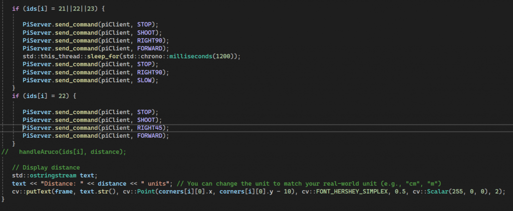
13. By the end of Friday I had coded a passable auto mode on the client side. This auto mode operated using distance detection using the arenas side ArUco codes. This resulted in two major issues. First the moving target and second command vs detection latency.
14. While this first auto mode was capable of going around the course it was much too inconsistent. This would not be able to pass inspection. I had been starting at Visual Studio for five days straight and my code had started to break down. This auto mode was unable to error correct, relied on receiving, processing, and sending data over a slow server, and could not hit the moving target in some positions. We decided to take a full break until Tuesday to improve our workflow and teamwork.
15. To be Continued…